Triple Ratio Balun PC Board Construction Photos
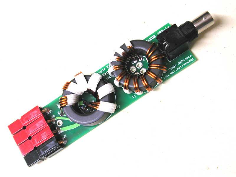
The Triple Ratio Balun PC Board Production Version
Note this photo is of the First Article which does not have color coded Powerpoles
Document Ver 0.11 (draft) 07/15/2004
This is a draft document. Please send Feedback to the author.
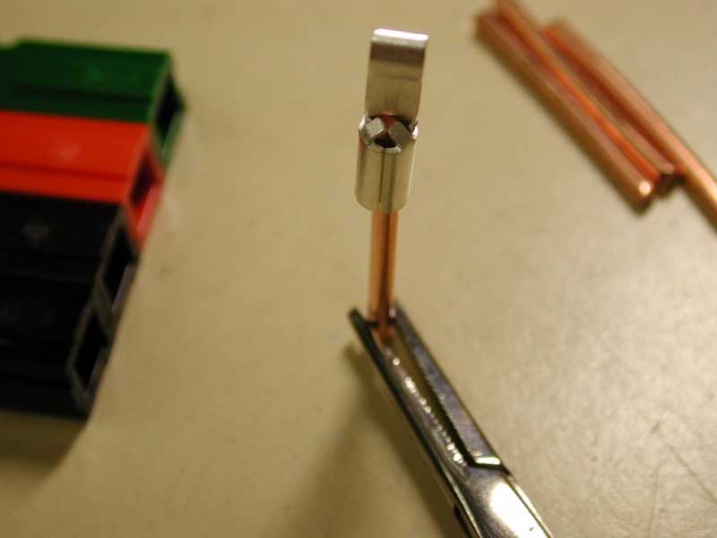
Preparing to solder an Anderson Powerpole pin.
Heat from the back side just below the holes in the tube top.
Apply solder carefully to the holes, it will flow inside.
Avoid getting significant solder on the outside of the tube.
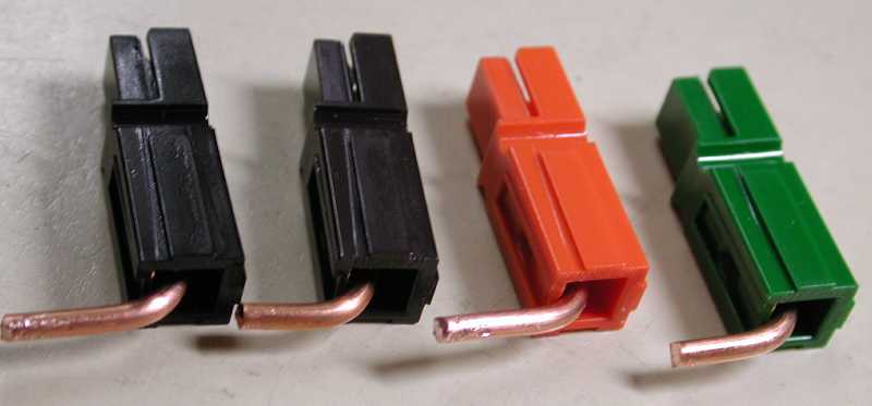
Pins installed, wires bent. Ready to connect together and load on PC board.
Bend the pins carefully, avoid placing too much strain on the plastic.
Note the direction of the bend, toward the side the contact is on.
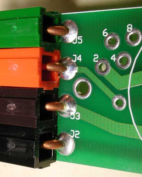
Anderson Powerpole connectors mounted to the board.
Note the bottom is black, the next brown, then orange and finally green at the top.
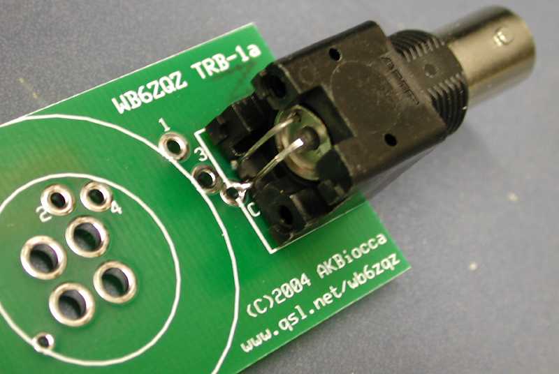
BNC Connector on PC Board.
Insure that the connector is firmly against the board when soldering.
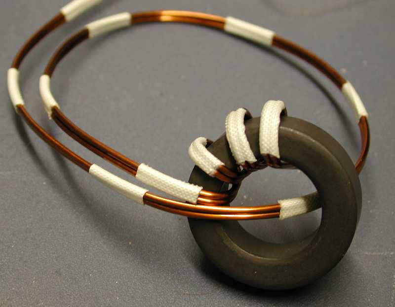
Like a coiling snake, winding the Bifilar toroid a couple of turns ahead
while tightening the winding reduces re-bending the wire.
Too much bending hardens the copper and makes the job more difficult.
Compare the winding to the PC Board and the photos to make it fit the hole pattern.
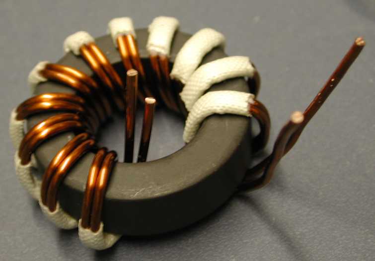
The completely wound Bifilar toroid, ready for lead stripping.
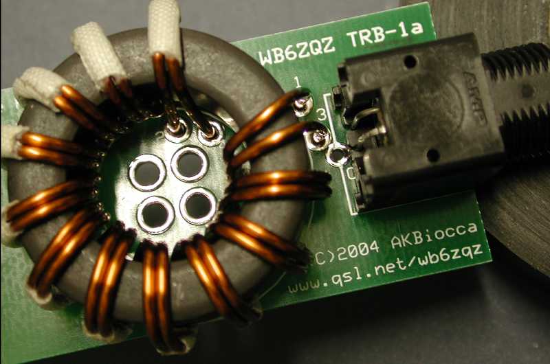
Bifilar Toroid mounted on PCB ready for soldering.
The extra holes in the center of the toroid are for cable ties if required.
They can be used for mounting or providing strain relief for the coax cable.
To restrain coax loop it around from the BNC under the board and tie it with small
cable ties.
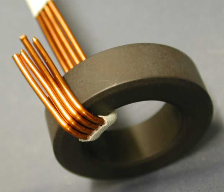
Starting the Quadrifilar winding.
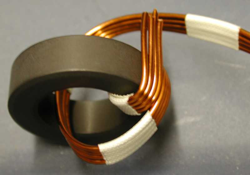
Continuing the Quadrifilar winding.
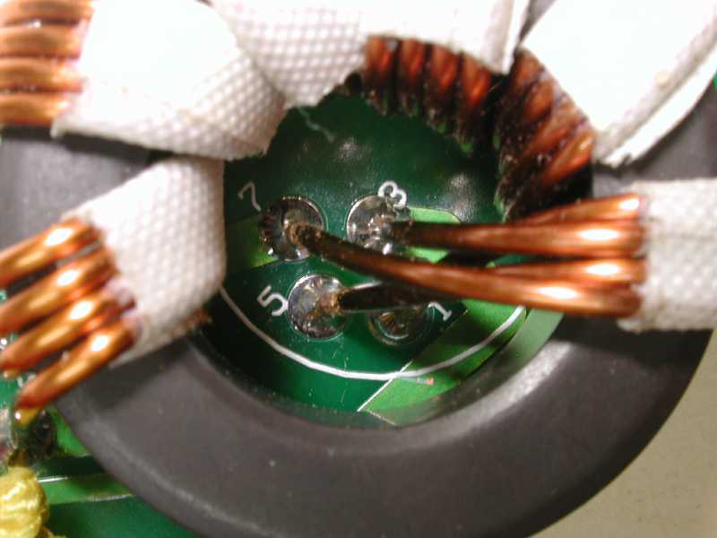
Inside terminations for the Quadrifilar core.
Note carefully the upper wire in the bundle crosses under to connect in hole 1
The second wire goes to hole 3.
The third wire to hole 5, the fourth to hole 7.
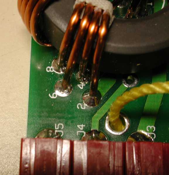
Outside terminations for the Quadrifilar core.
From a clockwise direction (right to left), the first wire is 2, then 4, 6, and 8.
This photo also shows the nylon cord threaded through the support hole.
This can be used to support the balun in the desired location.
Here is the adapter I made to connect to the Buddipole.
It is in the 50 ohm configuration now, with the phase reversed (red/black are swapped).
The phase should not matter but in some cases there is a small difference.
Lightweight Field Ready configuration, wrapped in a few layers of bubble wrap
held by a velcro cable tie.
Ready to deploy with the Buddipole Antenna System.
Schematic
TRB Home
TRB Construction Instructions and Pictures
WB6ZQZ Home Page
You may email author Alan Biocca via wb6zqz at arrl.net